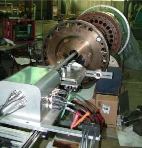
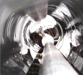
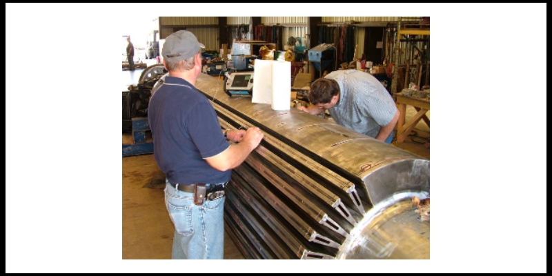
The Reinhart & Associates, Inc. (R&A) of generator rotors is performed using the B-SURE® (Boreside Surface and Ultrasonic Rotor Examination) system. The examination process is similar to the one used for steam turbine rotors except that in most cases a oil-tight boot needs to be installed in the main bore after the turbine end plug is removed.
The boot is installed to prevent any honing oil or turbine oil used during boresonics from contaminating the end windings under the exciter end retaining ring. The only time the boot is not installed is when the Copper bar is completely removed and the bore is accessible from both ends (turbine and exciter end). In some generator rotors there may be a set of flux bars that need to be removed immediately after plug removal and prior to boot installation.
Power honing and boreside NDE are performed and if no significant indications are detected, the boot is removed, the flux bars reinstalled (if flux bars are present), and a new replacement plug is installed. The results of the boresonics are used in conjunction with the rotor material properties, operating stress calculations, and fracture mechanics analysis to perform a life assessment of the rotor to determine current condition and suitability for future service. The life assessment yields a reinspection interval if no significant indications are detected or a recommendation is provided to change the rotor future operating conditions, rotor repair, or rotor replacement in case that significant indications are detected.
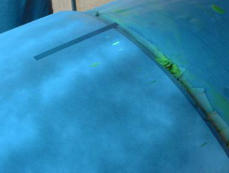
Generator retaining ring PT or WFMT
Generator retaining rings that are not ferromagnetic are examined using high sensitivity fluorescent liquid penetrant testing (HSFPT). The ferromagnetic rings are examined using wet fluorescent magnetic particle testing (WFMT).
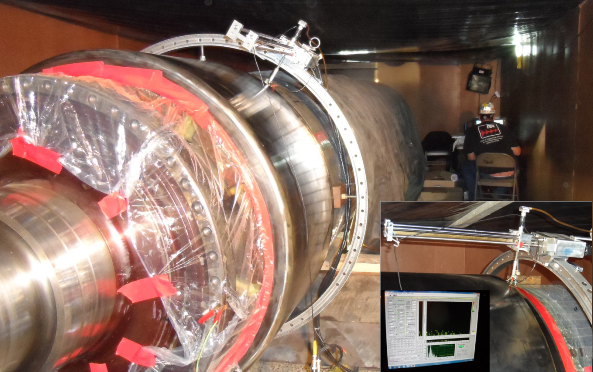
Generator retaining ring automated ultrasonic testing (AUT)
Automated ultrasonic testing (AUT) from the outside diameter (OD) surfaces is performed to interrogate the inside diameter (ID) of the retaining rings using refracted shear waves to provide ultrasonic images of the ID surface of the rings. The system is calibrated to be sensitive to the detection of a defect having dimensions of less than 0.015″ deep x 0.2″ long at a signal-to-noise ratio of 2 to 1. The ultimate examination sensitivity is dictated by the acoustic characteristics of the material volume.
A manual scan is performed prior to the automated scanning to render the ring ID profile and attenuation measurements. Form reflector discrimination examinations is performed utilizing specially designed ultrasonic search units used to differentiate ID reflectors in the “shrink-fit” areas from that of superfluous signals occurring below the ring bore. The scanning is done in 4 sectors around the ring and two sections designated as taper or shrink-fit area and ring body. The generator rotor is not required to be rotated since the scanner rotates around the ring circumference.
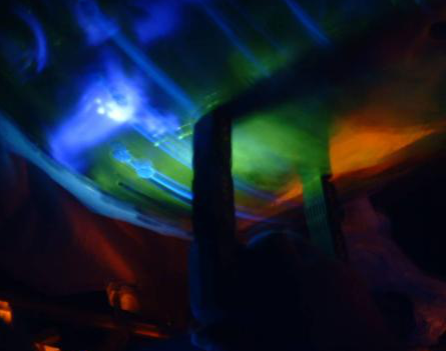
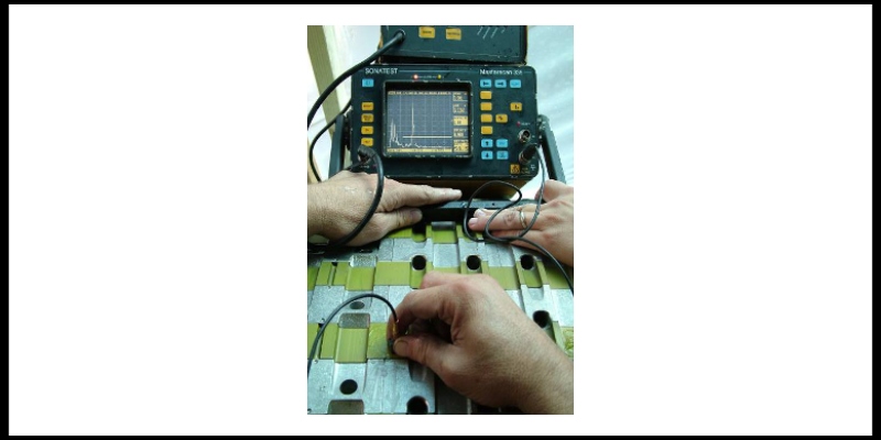
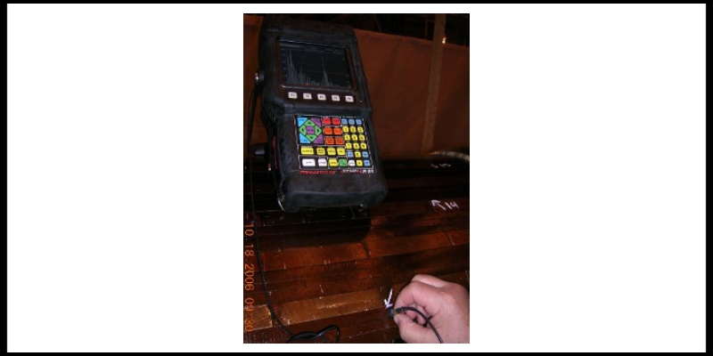
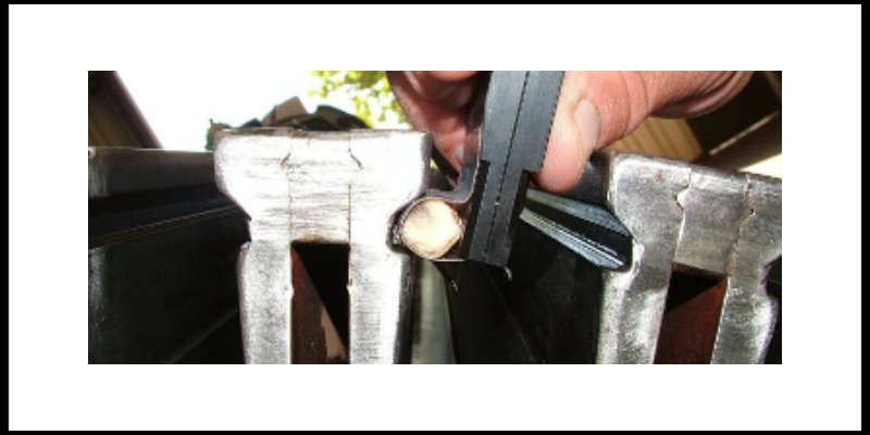
Generator dovetail slot and wedging testing
Some generator rotors are required to have their slot dovetails examined due to potential cracking starting on the periphery at the dovetail slots. The type of testing to be used to examine these areas depends on the amount of disassembly of the generator rotor. If the retaining rings and wedging are removed, then Eddy current testing (ET) combined with liquid penetrant testing (PT) is performed. If the retaining rings and wedging are installed, then ultrasonic testing (UT) or phased array ultrasonic testing (PAUT) are performed.
gen dt edited 4
gen dt edited 3
gen dt edited 2
gen dt edited 1
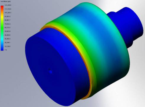
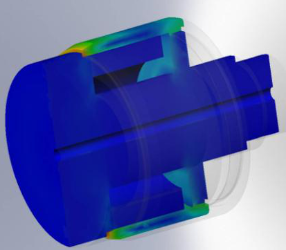
Generator rotor retaining ring stress analysis
The stress analysis of a generator retaining ring is performed using finite element analysis (FEA). R&A uses SolidWorks® simulation software to calculate the stress level and distribution caused by the centrifugal forces when rings are at rest or in service rotating at 3600 rpm or 3000 rpm or 1800 rpm depending on the grid requirement of each country and type of unit. The largest stress is located in the retaining ring shrink fit area especially when it is not rotating.